Electronic Fuse Schematic
The working of the circuit is very simple. By it can cut off the current immediately.
Low Value Manually Resettable Adjustable Electronic Fuse

2010 Chevrolet Impala Fuse Box Diagrams Ricks Free Auto

Wiring Diagram Product Manuals Schematic Electronics Png
The circuit uses only one transistor one scr one push button switch and two resistors.
Electronic fuse schematic. The schematic symbol for a fuse is. Electronic fuses are classified as either subminiature or miniature type fuses. This is perhaps one of the simplest electronic fuse circuit one can make.
As shown in the circuit it involves only few circuits and hence it is easy to construct and implement into our designs. Initially when the circuit is powered silicon controlled rectifier scr1 is. Fuses are devices containing a small piece of special wire that melts when the intensity of the current flowing through it for a certain period of time exceeds a set value thus protecting the rest of the electrical circuit overloads.
To solve this problem we build this electronic fuse limiter circuit so instead of plain fuses. Electronic fuse circuit fig. Thus wasting time.
Electronic fuse circuit diagram. Because often short to change the fuse every time. This is the standard and most common type of symbol found for fuses in schematic diagrams.
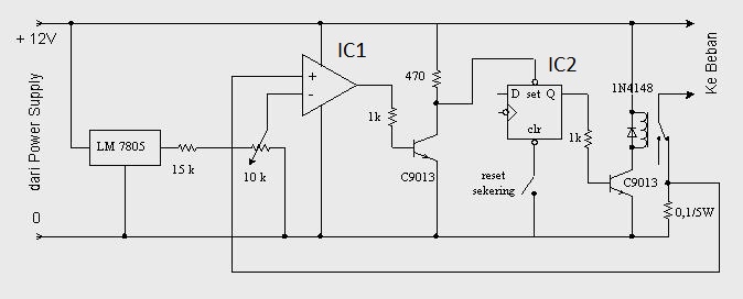
The circuit of electronic fuse uses a jfet type tl081 ic 1 op amp. Electronic fuse circuit operation. The subminiature fuse category includes the pico fuse the micro fuse the 23 x 8mm cartridge fuse the 36x10mm cartridge fuse and the surface mount fuse.
In some experiments electronic circuits require fuse protection. Electronic fuse circuit diagram. The voltage drop across the sensor resistor is weighed to activate the protection circuit.
A surface mount fuse is a subminiature fuse that is soldered directly on to a printed circuit board. The complete circuit diagram for an electronic fuse circuit is shown below. There automatic fuse circuit work with the reset button to restrict security electric current is usually used fuse or patron is dissolved when going short will drop out and must be replaced with a new one.
Initially the load current flows through scr and resistor r1the value of r1 is so selected that the maximum load current multiplied by the resistance of r1 is equal to 07 volts. Transistor t1 and resistor r1 form a 6 ma current source that together with zener diode d1 provides a constant voltage of 56 v with respect to the ve supply line. The circuit may be difficult.
When a short circuit as well. The given electronic fuse circuit is based on a poly fuse application which is a re settable fuse by itself. Here the circuit is constructed to monitor the operating current of a motor load which operates on 12v.
Fuses and electrical protection symbols. A small reference voltage is set up across the ics inverting input and in case the simple voltage fed across resistor r 1 in series with the load exceeds it the output is taken high and the relay energized to disconnect the load.

3nj62 In Line Switch Disconnectors With Fuses Up To 630 A

Electronically Designed Fuse For Power Supply Eeweb Community

Electronic Fuse For Dc Short Circuit Protection In 2020


Comments
Post a Comment